A Temperature Sensor Only Ever Measures Itself
The Only Thing It Can Measure
A temperature sensor reports the temperature of its own die. That is the whole of what it does, and it is worth stating plainly because everything that follows is engineering to make the die's temperature equal to the temperature of whatever you actually wanted to know about.
That is not a trivial goal. The die is soldered to copper, the copper runs across a board carrying components that dissipate power, the board sits in a plastic box, and the box is somewhere in the world absorbing sunlight and losing heat to the sky. Each of those is a thermal path, and each one pulls the die away from the air temperature you intended to measure.
Which is why a part specified to a tenth of a degree routinely lands two degrees out in a finished product, and why the resulting error is not fixable in software. A calibration offset can compensate a constant, and thermal errors are not constant: they depend on the sun, on how recently the radio transmitted, and on whether the room is warming or cooling.
The Three Ways Heat Reaches It
Conduction through the board is the largest and most controllable. Copper is an excellent thermal conductor, and a ground pour is a continuous sheet of it connecting your sensor directly to every warm component on the board. The worst offender is rarely the obvious one: a radio transmitting for a hundred milliseconds every quarter hour contributes almost nothing on average, while a linear regulator quietly dropping two volts at ten milliamps dissipates twenty milliwatts continuously and will happily hold a nearby sensor a degree or two above ambient forever. Anything with a duty cycle near unity matters; anything transient mostly does not.
Convection inside the enclosure is next. A sealed box has its own microclimate, warmer than outside during the day because it absorbs radiation and because the electronics are heating it, and always slower to respond than the air outside. A sensor in a sealed box measures the box, and the box is not what anyone asked about.
Radiation is the one that produces the spectacular errors. A device in direct sunlight absorbs energy at a rate that has nothing to do with air temperature, and an unshielded enclosure in the sun reads high by five to ten degrees on a light-coloured case and considerably worse on a dark one. At night the effect reverses, more weakly, as the device radiates to a cold sky and reads below ambient.
Decoupling on the Board
Most of the conducted error can be designed out at layout, and it costs nothing but attention.
The technique that does most of the work is to put the sensor on a peninsula. Place it near an edge of the board, then cut slots through the board on either side so that it is connected to the main body by a narrow neck rather than a wide sheet. Heat has to travel through that neck, and narrowing it by an order of magnitude reduces the conducted contribution by roughly the same factor. This one change is frequently the difference between a two-degree error and a tenth of one.
Alongside it, keep the copper away. No ground pour across the neck, no wide power traces, and the minimum number of signal traces that will do the job, routed thin. Four signals at a few thousandths of an inch carry very little heat. A pour carries a great deal.
Then think about which side of the board the heat is on. Putting the sensor on the opposite face from the regulator and the processor adds the board thickness to the path, which is not much, but combined with the neck it helps.
And leave the sensor's own aperture clear. Solder mask, conformal coating and adhesive over the sensing area all add a barrier that slows response and, in the case of coatings, can chemically damage a humidity element over time.
The layout decision that matters is not where the sensor is. It is how much copper connects it to everything else, and that is decided in an afternoon and impossible to change once the boards are made.
Time Constants and What They Cost
Thermal mass does not introduce error so much as delay, and whether the delay matters depends entirely on the question.
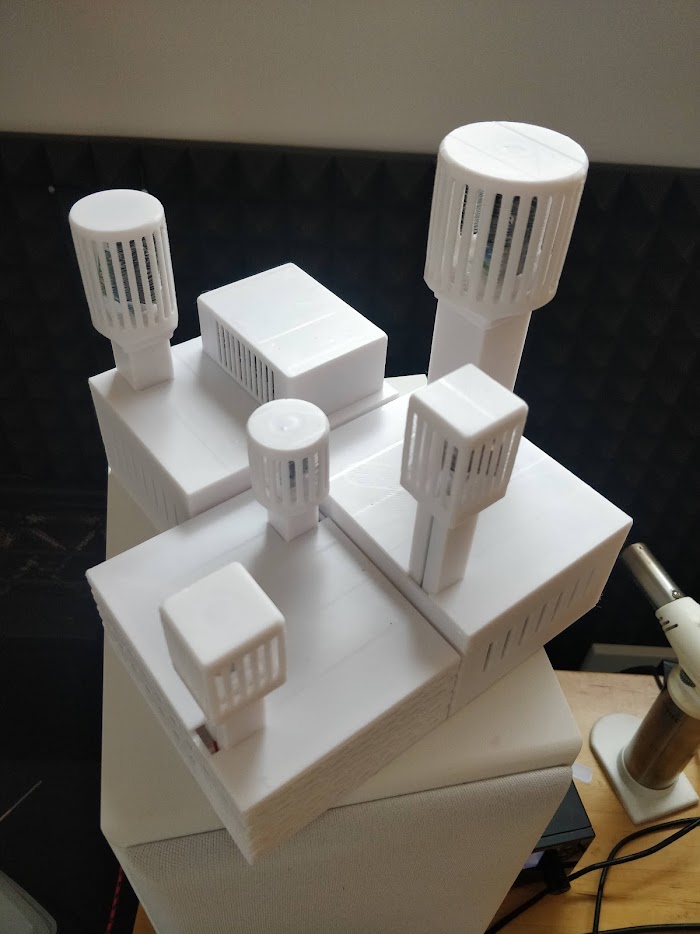
A bare sensor in moving air responds in seconds. Put it inside a small vented plastic enclosure and the time constant becomes minutes. Put it inside a substantial metal housing, or a housing with a potted assembly in it, and it can reach half an hour or more. None of those are wrong. A device with a thirty minute time constant reporting a seasonal trend is entirely fine, and the mass is actively helpful because it filters out transients nobody cares about.
The failure is a mismatch between the time constant and the application. A cold chain alarm that has to catch a freezer door left open, a process measurement where the transient is the signal, or a control loop that will oscillate if its feedback is delayed all need a fast sensor, and giving them a heavy one produces a system that appears to work and misses exactly the events it was installed for.
Worth knowing: the sensor's own package, the filter cap over it and the enclosure around it each add their own lag, and they add rather than the largest dominating. A slow cap inside a slow box is slower than either.
The practical approach is to decide the required response time at specification stage, then design outward from it. Fast means a small exposed sensor, minimal cap, and airflow, possibly forced. Slow is easy and is what you get by default.
Shielding Outdoors
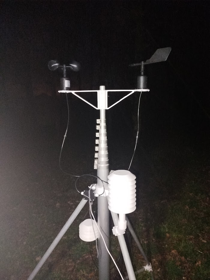
Any outdoor air temperature measurement needs a radiation shield, and a lid is not one.
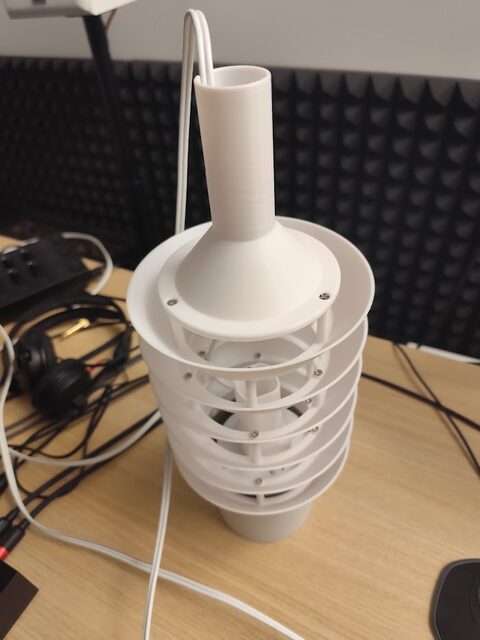
The standard arrangement is a stack of louvred plates, white, with air able to move horizontally between them while no straight line exists from the sky or the sun to the sensor. The gaps are what makes it work: they let ambient air wash through continuously so the sensor sees moving outside air rather than a trapped pocket. A closed white box is dramatically better than a closed black box and still considerably worse than a proper screen.
The remaining error in a passive screen appears on still, sunny days, when there is not enough natural airflow to carry away the heat the screen itself has absorbed, and readings run a few tenths to a degree high. Forcing air through with a small fan removes most of that and is what a serious meteorological installation does, at the cost of continuous power and a moving part. For most deployments a well-made passive screen is the right trade, and it is worth knowing which direction its residual error goes.
Materials matter more than they look. A shield printed or moulded in a polymer that yellows and embrittles under ultraviolet will change its reflectance over a couple of seasons, which means the measurement drifts for reasons nothing in the system can detect. A UV-stable material and a light colour are part of the measurement chain, not cosmetic choices, which is one reason the enclosure material decision deserves more thought than it usually gets.
And then there is placement, which no amount of shield design compensates for. A sensor mounted on a south-facing wall is measuring a wall that has been in the sun all day. A sensor above dark tarmac in summer reads the tarmac. Standard practice puts the instrument over short vegetation at a defined height, away from buildings, and the reason it is standard is that everything else gives a number that is real and is not the air temperature of the area.
Telling a Thermal Error From a Calibration One
They look similar in a spreadsheet and have completely different fixes, so it is worth knowing how to separate them.
A calibration error is constant. The device reads the same amount high at two in the morning as at two in the afternoon, in January and in July, and the offset does not care what else is happening. That is a genuine offset and a correction constant fixes it.
A thermal error varies with conditions, and the shape of the variation names the cause. An error that appears in daylight and vanishes at night is radiative, and the answer is shielding or repositioning. An error that grows when the device is transmitting more often, or after a firmware change that increased the reporting rate, is self-heating. An error that appears only when the room is changing temperature quickly, and disappears once it settles, is thermal mass, and it is a lag rather than an offset. An error that varies with humidity is usually the temperature error underneath a humidity reading, for the reasons in the humidity article.
The diagnostic that answers all of these at once is a reference instrument sitting next to the device for a few days, logging at the same interval, through at least one sunny day and one still night. Plot the difference between the two against time of day and the pattern names the mechanism. It takes an afternoon to set up and it prevents the usual outcome, which is a fleet of replaced hardware and an unchanged error.
Where This Effort Is Not Warranted
Plenty of measurements do not justify any of this, and it is worth saying so.
If the requirement is to detect a freezer failing or a room falling below freezing, a couple of degrees of error changes nothing, and a sensor bolted anywhere convenient is the right engineering. Over-designing here spends money on precision nobody will use.
If the device is indoors, out of the sun, and drawing microamps between readings, the conducted and radiative paths are both small, and reasonable layout is enough without slots and peninsulas.
The effort is warranted when the measurement drives a control loop, when it will be compared against another site or another year, when it feeds a report somebody might dispute, or when it is outdoors. Those are the cases where an unexamined two-degree offset quietly invalidates everything built on top of it.
What I Provide
This is design work rather than a product, and it happens at schematic and enclosure stage: the sensor placed on its own peninsula with the copper deliberately starved, the warm components positioned away from it, the vent path through the housing planned so the sensor sees outside air, and the shield or filter chosen against the response time the application actually needs.
Where devices are already built and the numbers are being questioned, I run the co-location described above and identify which mechanism is responsible, because radiative error, self-heating and thermal lag produce plausible data and each needs a different remedy. That distinction is usually worth more than a new sensor, and it is a great deal cheaper than replacing a fleet that was never faulty.
Does this describe your project?
If any of the above sounds like something you are dealing with, tell me about it. You will get a straight read on the right approach for your situation, and the first conversation costs nothing.
Start a conversationPrefer to see the finished thing first? There is one running on real devices